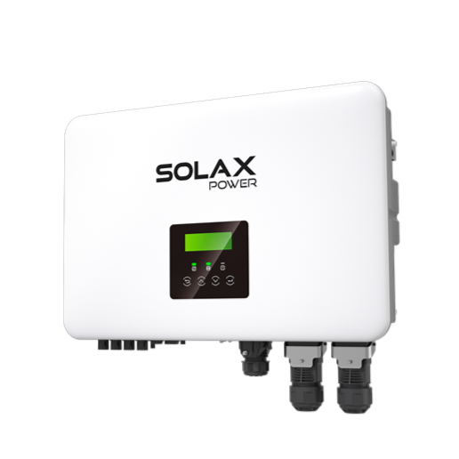
Smart Management Assured Reliability
V2G/V2H ready for smart home energy integration* Smart Schedule, Smart Scene, and 7×24h TOU
VPP ready with a variety of compatibility(OpenADR, IEEE2030.5, FCAS, API)*
Wireless meter compatibility
Support whole-home load without extra devices
High Performance
20A DC input per MPPT with 4 trackers 200% PV oversizing and high power capacity Low PV start-up voltage of 50V
Up to 200% EPS output for 10s UPS-level switchover time <10ms Type II SPD on AC&DC side Optional AFCI protection*
Flexible Adaptability
Dual battery ports & 2-in-1 function for expansion Dedicated multi-device connections for streamlined cabling Functional and stylish wiring cover
Microgrid and generator compatible for resilient off-grid solutions
Efficiency Curve Circuit Diagram
* Feature to be upgraded in the future
100%
98%
96%
94%
92%
90%
88%
86%
5% 10% 20% 30% 50% 75% 100%
Load (%)
260V
360V
460V
510V
+86 571-56260008
*V1.6 Information may be subject to modify without notice. 650.00081.00
X1-VAST-5K
X1-VAST-6K
X1-VAST-8K
X1-VAST-10K
| PV INPUT | ||||
| Max. recommended PV array power | 10 kWp | 12 kWp | 16 kWp | 20 kWp |
| Max. PV input voltage① | 600 V | |||
| Nominal PV input voltage | 360 V | |||
| Operating voltage range | 40 ~ 560 V | |||
| MPPT voltage range② | 40 ~ 560 V | |||
| Start-up voltage | 50 V | |||
| No. of MPP trackers / Strings per MPP tracker | 3 / (1 / 1 / 1) | 4 / (1 / 1 / 1 / 1) | ||
| Max. input current per MPPT(MPPT1/2/3) | 20 A / 20 A / 20 A | 20 A / 20 A / 20 A / 20 A | ||
| Max. input short circuit current per MPPT(MPPT1/2/3) | 25 A / 25 A / 25 A | 25 A / 25 A / 25 A / 25 A | ||
| AC INPUT & OUTPUT(ON-GRID) | ||||
| Rated output power | 4999 W | 6000 W | 8000 W | 9999 W |
| Rated output current | 21.8 A | 26.1 A | 34.8 A | 43.5 A |
| Max. output apparent power | 4999 VA | 6000 VA | 8000 VA | 9999 VA |
| Max. output continuous current | 21.8 A | 26.1 A | 34.8 A | 43.5 A |
| Max. AC input apparent power | 14500 VA | |||
| Max. AC input current | 63 A | |||
| Adjustable Power Factor range | ~ 1 (0.8 lagging to 0.8 leading) | |||
| THDi (rated power) | < 2% | |||
| BATTERY | ||||
| Battery type | Lithium | |||
| Battery voltage range | 80 ~ 480 V | |||
| Max. charge / discharge current③ | 50 A (25 A × 2) | |||
| EPS (OFF-GRID) OUTPUT (WITH BATTERY) | ||||
| Rated EPS output voltage, frequency | 230 V, 50 Hz / 60 Hz | |||
| Rated EPS output power | 5000 VA
(4999 VA for Australia) |
6000 VA | 8000 VA | 10000 VA
(9999 VA for Australia) |
| Peak EPS output power | 2 times of rated power, 10 s | |||
| Switchover time | < 10 ms | |||
| EFFICIENCY | ||||
| Max. efficiency | 97.6% | |||
| ENVIRONMENT LIMIT | ||||
| Ingress protection | IP66 | |||
| Operating ambient temperature range④ | -35 ~ 60°C | |||
| Max. operating altitude | 3000 m | |||
| Relative humidity | 4 ~ 100% RH (condensing) | |||
| GENERAL | ||||
| Dimensions (W × H × D) | 590 × 400 × 180 mm | |||
| Net weight | 28 ± 2 kg | |||
| Cooling concept | Nature cooling | |||
| Communication interfaces | CT/Meter (optional), External control RS485, Dongle interfce , DRM | |||
| Topology | Transformerless | |||
| Certificates and approvals | EN / IEC62109 -1 / -2, AS / NZS 4777, G99, EN 50549-10, BR140, IEC61727, IEC 61683, RD1699, NRS 097-2 -1, PEA / MEA, VFR2019 | |||
| PROTECTION | ||||
| Protections | DC isolation protection, DC reverse-polarity protection, Residual current detection, Over temperature protection | |||
| Active anti-islanding method | Frequency shift | |||
| Surge protection (DC / AC) | DC: Type II, AC: Type II | |||
| Arc-fault circuit interrupter (AFCI) | Optional | |||
① The maximum input voltage is the upper limit of the DC voltage. Any higher input DC voltage would probably damage the inverter
② Input voltage exceeding the MPPT voltage range may trigger inverter protection
③ If each of the two battery ports is connected to a separate battery, it’s 25A per port. If one port is connected to a single battery, it’s 30A. If both ports are connected to a single battery using a 2-in-1 splitter cable(sold separately), it’s 50A.
④ Derating above +45°C

